
A practical engineering guide to common VFD faults, including overcurrent, overvoltage, overload, ground fault, overtemperature, communication failures, diagnostic checks, and corrective actions.
Introduction
A Variable Frequency Drive is designed to monitor the motor, electrical supply, load conditions, and its internal components continuously.
When an abnormal condition is detected, the VFD may issue a warning or stop the motor to protect the drive, motor, cables, and connected equipment.
A fault does not always mean that the VFD is damaged. In many cases, the trip is caused by an incorrect parameter, excessive mechanical load, unstable power supply, damaged motor cable, poor ventilation, or an unsuitable acceleration or deceleration time.
Effective troubleshooting starts by identifying the fault category and checking the complete application rather than replacing the drive immediately.
Common VFD Fault Categories
VFD faults can generally be divided into five main categories.
Electrical Faults
These faults are related to the incoming supply, DC bus, output voltage, or phase conditions.
Common examples include:
- Overvoltage
- Undervoltage
- Input phase loss
- Output phase loss
- Supply imbalance
Motor and Load Faults
These faults occur when the motor or connected equipment requires more current or torque than the system can safely provide.
Common examples include:
- Overcurrent
- Motor overload
- Drive overload
- Motor stall
- Mechanical blockage
Thermal Faults
Thermal faults occur when the VFD or motor temperature exceeds the permitted operating level.
Common examples include:
- Drive overtemperature
- Motor overtemperature
- Cooling fan failure
- Blocked ventilation
- High ambient temperature
Communication and Feedback Faults
These faults are related to communication between the VFD and external control equipment.
Common examples include:
- Modbus communication timeout
- PLC communication failure
- Encoder feedback loss
- Pressure sensor signal loss
- Analog feedback failure
Internal Hardware Faults
These faults may indicate a problem with the internal electronic components of the VFD.
Common examples include:
- IGBT fault
- Current measurement fault
- DC bus fault
- Control board fault
- Internal communication fault
Internal hardware faults should normally be investigated by qualified service personnel.
Overcurrent Fault
What Does It Mean?
An overcurrent fault occurs when the VFD output current rises above the permitted protection level.
The fault may appear during acceleration, normal operation, deceleration, or immediately after a start command.
Possible Causes
- Acceleration time is too short
- Sudden increase in mechanical load
- Motor or driven equipment is blocked
- Motor cable is short-circuited
- Motor winding is damaged
- Incorrect motor parameters
- VFD rating is too small for the application
- Incorrect control mode
- Output contactor switching while the VFD is running
What Should Be Checked?
- Motor nameplate current
- Actual output current
- Acceleration time
- Motor and cable insulation
- Mechanical condition of the load
- Motor parameter settings
- VFD capacity and overload rating
- Output wiring connections
Corrective Actions
Increase the acceleration time when the fault occurs during starting.
Check the motor and driven equipment for mechanical blockage or excessive load.
Verify the motor nameplate data entered into the VFD.
Inspect the output cable and motor insulation before restarting the system.
Do not repeatedly reset an overcurrent fault without identifying the cause.
Overvoltage Fault
What Does It Mean?
An overvoltage fault occurs when the VFD DC bus voltage rises above the permitted protection level.
This fault commonly occurs during motor deceleration because the motor can return regenerative energy to the VFD.
Possible Causes
- Deceleration time is too short
- High incoming supply voltage
- Load has high inertia
- Motor is being driven by the connected machine
- Braking resistor is missing or incorrectly selected
- Braking unit is not operating correctly
- Supply voltage contains switching surges
What Should Be Checked?
- Incoming voltage
- DC bus voltage
- Deceleration time
- Load inertia
- Braking resistor and braking unit
- Frequency of start and stop cycles
- Regenerative operating conditions
Corrective Actions
Increase the deceleration time.
Use controlled stopping or coast-to-stop when suitable for the application.
Install or verify the braking resistor when rapid stopping is required.
Check that the supply voltage remains within the VFD operating range.
Overload Fault
What Does It Mean?
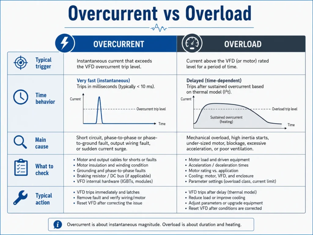
An overload fault indicates that the motor or VFD has operated above its permitted thermal loading for a specific period.
Unlike an instantaneous overcurrent fault, overload protection is normally based on current level and operating time.
Possible Causes
- Continuous excessive mechanical load
- Motor is undersized
- VFD is undersized
- Incorrect motor rated current
- Motor operates at low speed for a long period
- Insufficient motor cooling
- Frequent acceleration and deceleration
- High starting torque requirement
What Should Be Checked?
- Motor current under normal operation
- Motor nameplate data
- VFD rated output current
- Load operating cycle
- Motor temperature
- Cooling conditions
- Minimum operating speed
- Torque requirements
Corrective Actions
Reduce the mechanical load where possible.
Verify that the motor and VFD are correctly sized.
Correct the motor rated current and protection parameters.
Provide independent motor cooling when continuous low-speed operation reduces the effectiveness of the motor-mounted fan.
Ground Fault
What Does It Mean?
A ground fault occurs when current flows from the motor circuit to earth through damaged insulation, incorrect wiring, moisture, or another unintended path.
Possible Causes
- Damaged motor cable
- Motor winding insulation failure
- Moisture inside the motor terminal box
- Loose cable strands touching the enclosure
- Incorrect grounding
- Excessive cable capacitance
- Long motor cable
- Damaged output filter
What Should Be Checked?
- Motor cable insulation
- Motor winding insulation
- Motor terminal connections
- Cable glands and termination points
- Grounding conductor
- Moisture or contamination
- Cable length and installation method
Corrective Actions
Isolate the VFD before performing insulation tests.
Disconnect the motor cable from the VFD before using an insulation resistance tester.
Inspect the complete motor cable and motor terminal box.
Repair or replace damaged cables and motors before restarting the VFD.
Never apply insulation test voltage directly to the VFD output terminals.
Overtemperature Fault
What Does It Mean?
An overtemperature fault occurs when the internal temperature of the VFD exceeds its permitted operating limit.
Possible Causes
- High ambient temperature
- Blocked ventilation openings
- Cooling fan failure
- Dirty heatsink
- Insufficient panel ventilation
- Incorrect clearance around the VFD
- Continuous operation near maximum current
- High switching frequency
What Should Be Checked?
- Ambient temperature
- VFD heatsink temperature
- Cooling fan operation
- Panel filters and ventilation openings
- Installation clearance
- Output current
- Switching frequency
- Panel cooling system
Corrective Actions
Clean the ventilation openings and heatsink.
Replace damaged cooling fans.
Improve control panel ventilation.
Reduce the switching frequency when technically acceptable.
Verify that the VFD is not continuously operating above its rated current.
Communication and Feedback Faults
What Do They Mean?
Communication faults occur when the VFD loses data exchange with a PLC, HMI, controller, encoder, or field sensor.
Feedback faults occur when the VFD receives an invalid, missing, or out-of-range signal.
Possible Causes
- Incorrect communication settings
- Wrong device address
- Baud rate or parity mismatch
- Reversed RS-485 polarity
- Damaged communication cable
- Poor cable shielding
- Missing termination resistor
- PLC communication timeout
- Sensor power supply failure
- Broken analog signal cable
What Should Be Checked?
- Communication protocol
- Device address
- Baud rate, data bits, parity, and stop bits
- Cable polarity and shielding
- Termination resistance
- PLC and VFD timeout settings
- Sensor supply voltage
- Analog input signal
- Encoder wiring
Corrective Actions
Match the communication parameters between all connected devices.
Separate communication cables from high-power motor cables.
Use shielded twisted-pair cables where required.
Verify the sensor signal using a suitable measuring instrument.
Configure the required VFD response to communication loss, such as stopping, maintaining the last speed, or operating at a preset frequency.
The selected response must be suitable for the safety requirements of the application.
Internal VFD Faults
Internal faults may involve the power module, DC bus, current sensors, cooling system, control board, or internal communication circuits.
Repeated internal faults should not be cleared continuously.
The following actions are recommended:
- Record the complete fault code
- Record the operating condition when the fault occurred
- Check the supply and motor circuit
- Allow the DC bus to discharge completely
- Restart only according to the manufacturer’s instructions
- Contact qualified service personnel if the fault returns
Do not open or repair the internal power section unless the work is performed by trained and authorized personnel.
VFD Troubleshooting Procedure
A structured troubleshooting process helps reduce downtime and prevents unnecessary component replacement.
Step 1: Record the Fault
Record the fault code, operating frequency, motor current, DC bus voltage, and operating condition.
Identify whether the fault occurred during starting, acceleration, normal running, deceleration, or stopping.
Step 2: Inspect the Installation
Check the incoming supply, motor cable, grounding, terminal tightness, ventilation, and signs of overheating or damage.
Step 3: Check the Mechanical Load
Confirm that the motor and connected equipment rotate freely and that the load is not blocked or overloaded.
Step 4: Verify the Parameters
Review the motor nameplate data, acceleration time, deceleration time, control mode, current limits, minimum speed, maximum speed, and protection settings.
Step 5: Perform Electrical Measurements
Measure the incoming voltage, phase balance, motor current, feedback signals, and other relevant values using suitable instruments.
Step 6: Test the System Safely
After correcting the suspected cause, restart the system under controlled conditions and monitor the operating values.
Step 7: Review the Fault History
Repeated faults may indicate an operating pattern or application problem that cannot be identified from a single trip.
Engineering Checklist
Before replacing a VFD, verify the following:
- Incoming voltage is within the permitted range
- All input phases are available and balanced
- Motor nameplate data is entered correctly
- Motor current is within the expected range
- Acceleration and deceleration times are suitable
- Motor and cable insulation are healthy
- Grounding is correctly installed
- Cooling fans are operating
- Ventilation openings are clean
- Ambient temperature is acceptable
- Mechanical load is not blocked
- Communication settings are correct
- Feedback signals are valid
- Fault history has been reviewed
- VFD capacity is suitable for the application
Safety Considerations
VFDs can retain hazardous DC voltage after the incoming supply has been disconnected.
Before inspection or maintenance:
- Disconnect and isolate the incoming power
- Apply lockout and tagout procedures
- Wait for the manufacturer’s specified discharge time
- Verify that the DC bus voltage has reached a safe level
- Follow the VFD manufacturer’s service instructions
- Use qualified personnel for electrical testing and repair
Do not rely only on the keypad display to confirm that the VFD is electrically safe.
Conclusion
Most VFD faults are protection responses rather than immediate evidence of equipment failure.
Overcurrent, overvoltage, overload, ground fault, overtemperature, and communication faults may result from the power supply, motor, cables, mechanical load, parameter settings, environmental conditions, or installation quality.
A systematic troubleshooting approach should include fault classification, visual inspection, parameter verification, electrical measurements, mechanical checks, and controlled testing.
Correct diagnosis reduces unnecessary downtime, prevents repeated trips, and helps protect the VFD, motor, and connected equipment.